Hey there! It has been a while since I switched to hardware mode. It all started when I found a NodeMCU that I used for some random project from my cupboard a few months back. I was in search of something interesting to make out of it since then. And a few days ago, I came across a 128x64 OLED display. So, I went straight to the local hardware store and bought a bunch of stuff that I needed to get started.
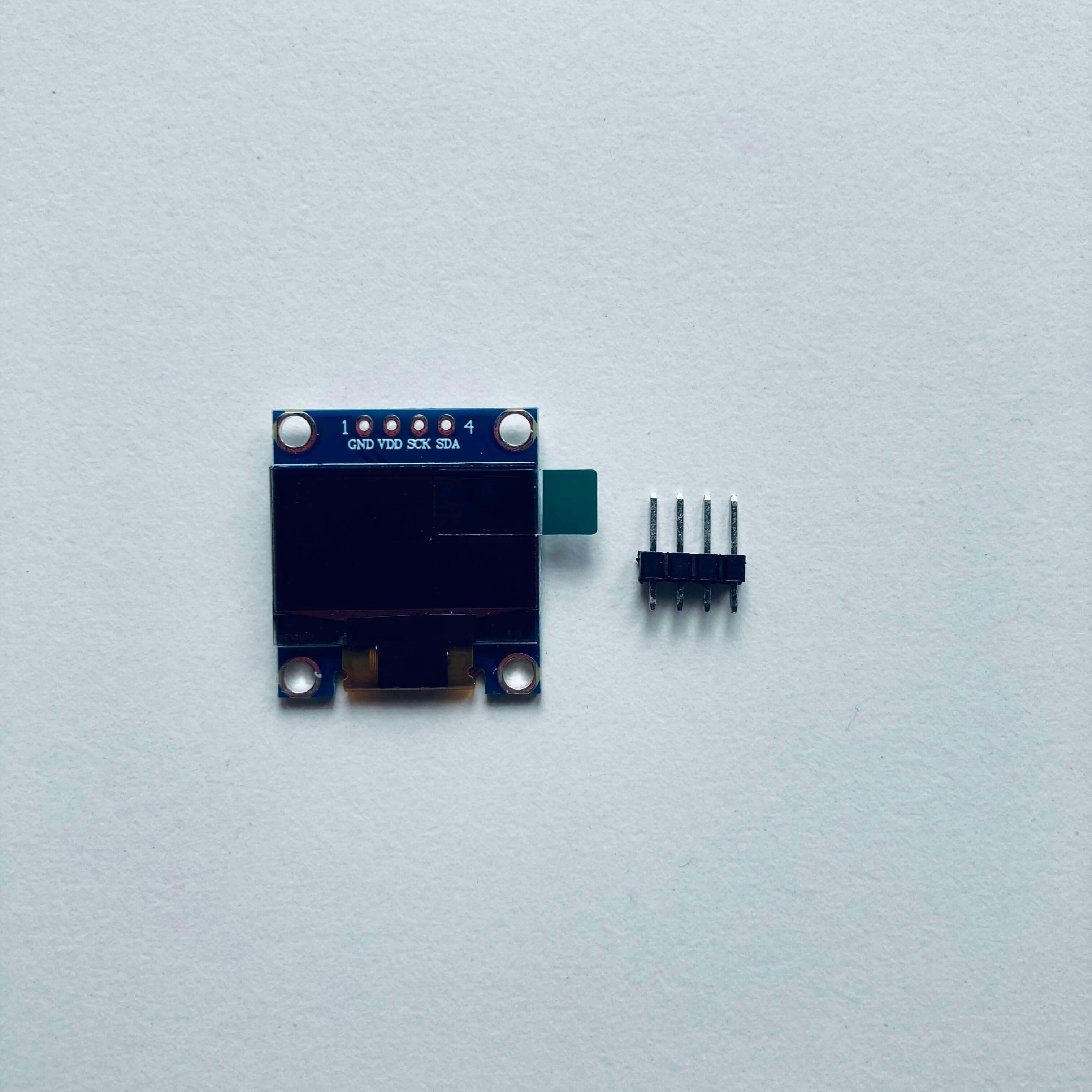
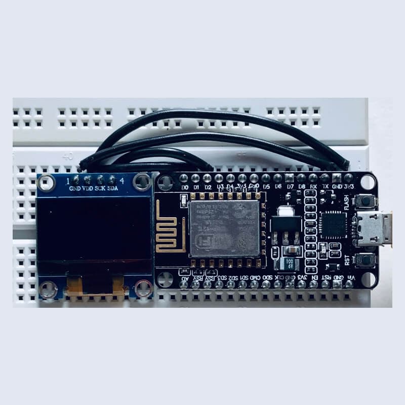
- 128x64 OLED display module
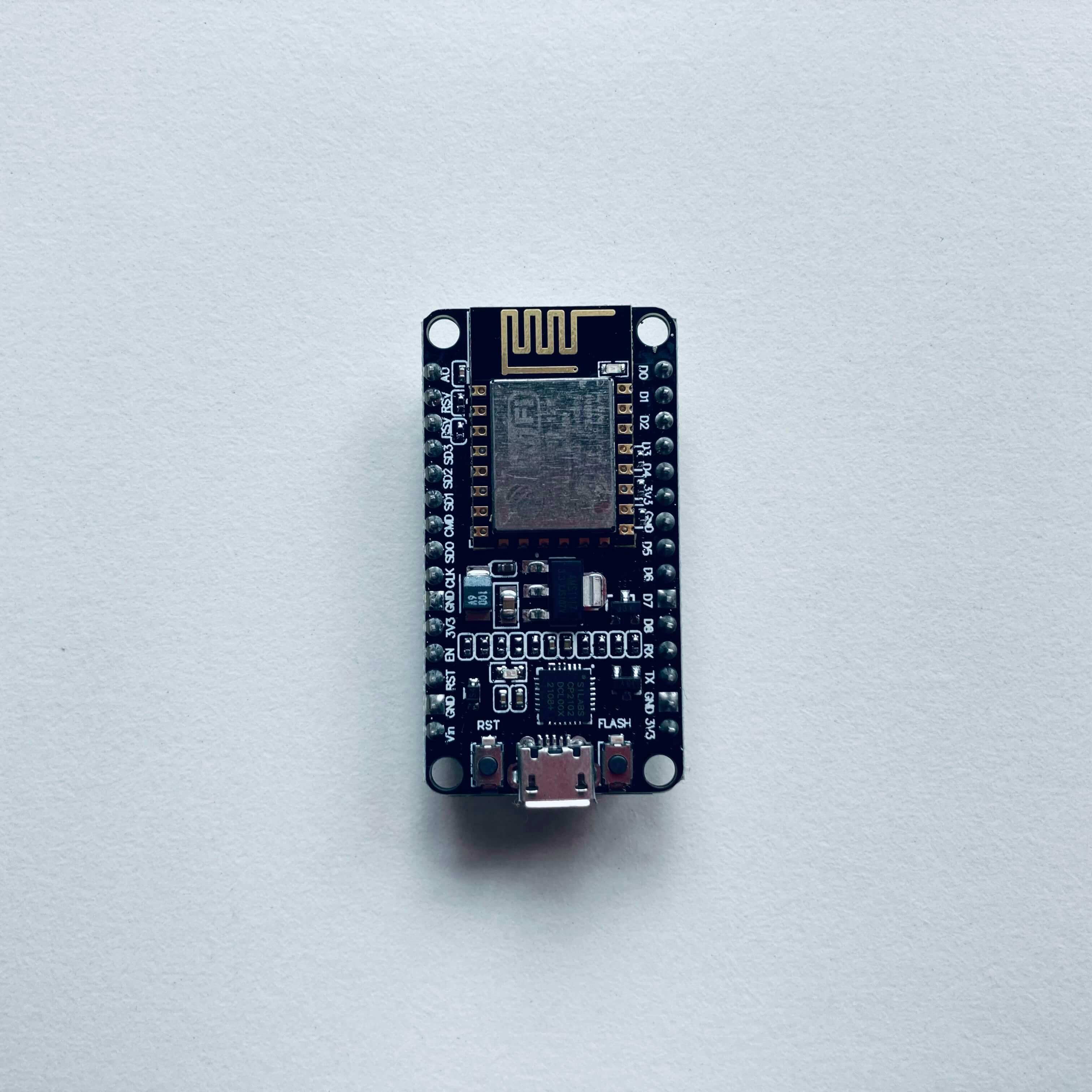
- NodeMCU ESP8266
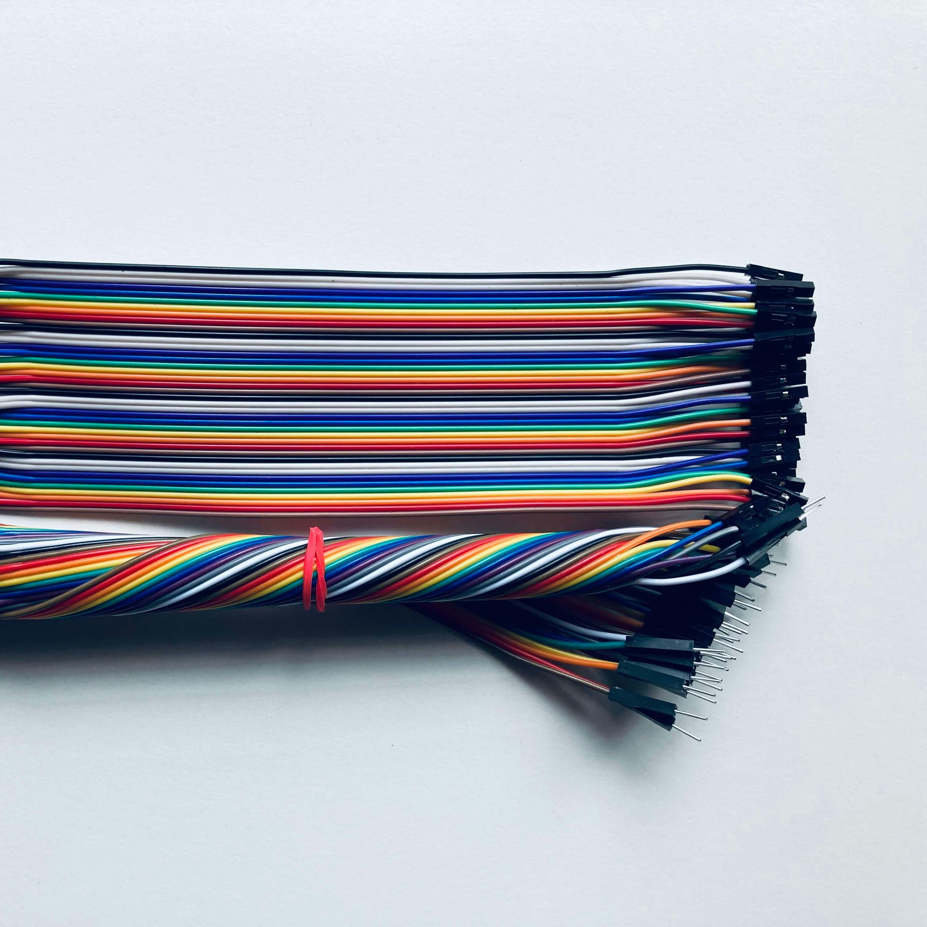
- Ribbon cables
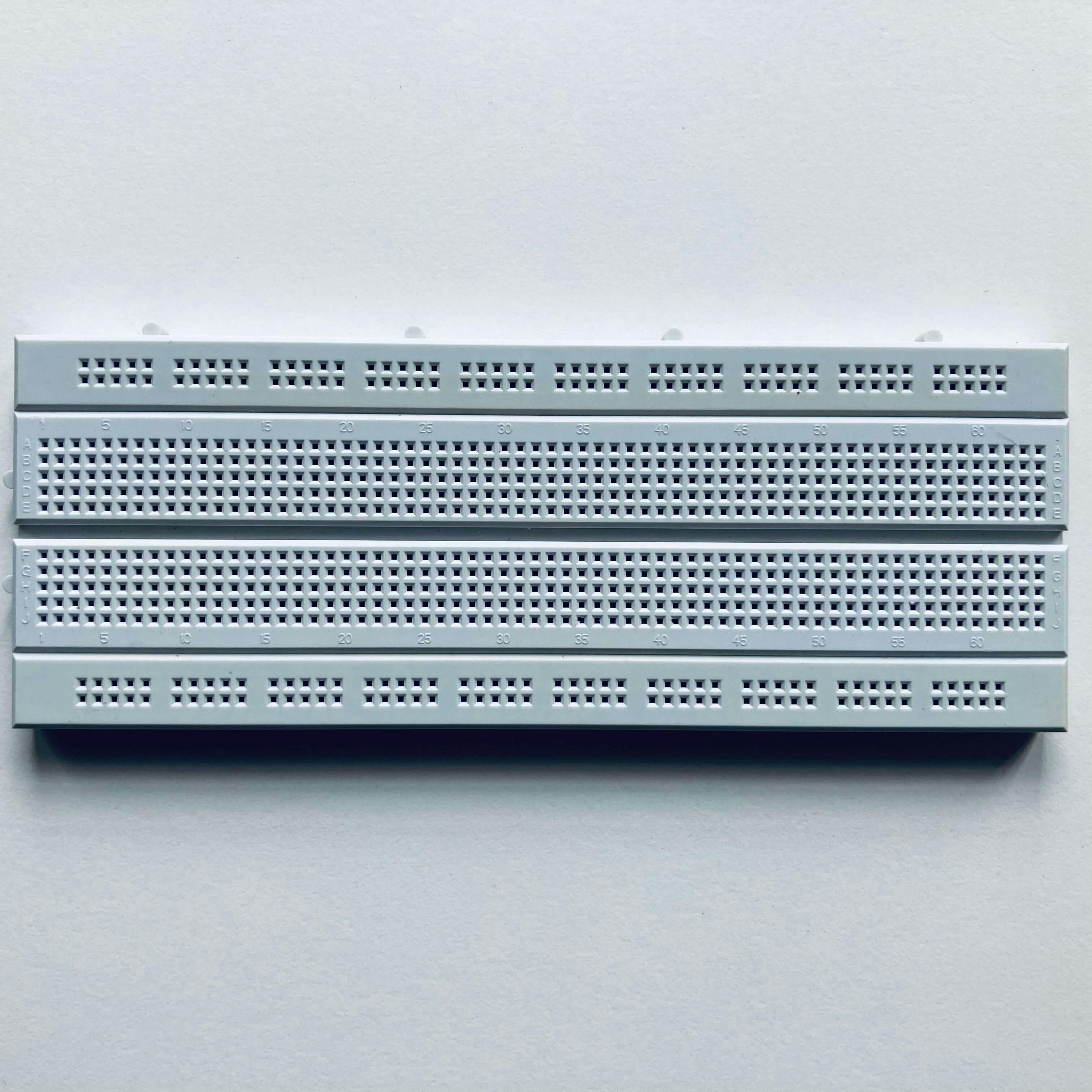
- Breadboard
So, let us dive into some open-source IoT!
What is NodeMCU?
The Node MicroController Unit is an open-source software and hardware development environment that is built around a very inexpensive SoC called the ESP8266. NodeMCU can transfer data using the Wi-Fi protocol. It also provides some of the most important features of microcontrollers such as GPIO, PWM, ADC, etc. It is an Arduino with onboard WiFi.
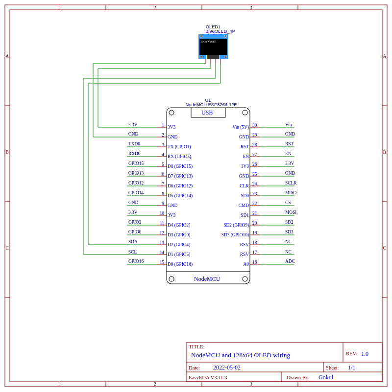
The OLED display module can be interfaced with any microcontroller using the SPI/I2C protocol. The OLED module that I bought had 4 pins GND, VDD, SCK, and SDA. The module is controlled by a SSD1306 driver.
The I2C (Inter-Integrated-circuit / I-squared-C) protocol is a serial communication protocol, so data is transferred bit by bit along a single wire which is synchronized by a clock signal shared between master and slave. The master is the one in control of the clock. It is also known as the TWI(two wired interfaces). The SCK/SCL stands for the clock line and SDA stands for the data line.
Setting things up
- Download the IDE from the official website
- Add all the ESP boards to the IDE
- Add the link provided by the GitHub page to Additional boards in Preferences
- Then go to Boards in Tools and search for ESP8266 and install it
- We need the Adafruit's SSD1306 library to easily access and control the controller. Head over to Sketch > Include Library > Manage Libraries and from the dialog box, search for adafruit ssd1306 and install it. In addition to that, we need the Adafruit BusIO library and Adafruit GFX library (These are dependencies of the SSD1306 library, there might be a pop-up requesting to install these). Then go ahead and install the I2Cdetect library.
Now let's wire up the components.
Note:
| NodeMCU Pins   |      Corresponding Arduino pins      |
|----------------|--------------------------------------|
|       D0       |                  16                  |
|       D1       |                  5                   |
|       D2       |                  4                   |
|       D3       |                  0                   |
|       D4       |                  2                   |
|       D5       |                  14                  |
|       D6       |                  12                  |
|       D7       |                  13                  |
|       D8       |                  15                  |
|       D9       |                  3                   |
|       D10      |                  1                   |
Now we have to find the address where the display is connected. To do that head to:
File > Examples > I2Cdetect, upload the script to the NodeMCU and open up the serial monitor.
Arduino Serial monitor

     0  1  2  3  4  5  6  7  8  9  a  b  c  d  e  f
00:          -- -- -- -- -- -- -- -- -- -- -- -- --
10: -- -- -- -- -- -- -- -- -- -- -- -- -- -- -- --
20: -- -- -- -- -- -- -- -- -- -- -- -- -- -- -- --
30: -- -- -- -- -- -- -- -- -- -- -- -- 3c -- -- --
40: -- -- -- -- -- -- -- -- -- -- -- -- -- -- -- --
50: -- -- -- -- -- -- -- -- -- -- -- -- -- -- -- --
60: -- -- -- -- -- -- -- -- -- -- -- -- -- -- -- --
70: -- -- -- -- -- -- -- --
The output will look something similar to the above. The inference from the output is that the display is connected to 0x3C.
In the Adafruit_SSD1306.h file, we need to uncomment the display specification. This file can be found in Arduino > Libraries > Adafruit_SSD1306 folder which is in the Documents folder(Windows) or the Arduino folder in the home folder(Linux)
For me, as I am using a 128x64 display, the line I have to uncomment is...
#define SSD1306_128_64Now restart the IDE for the changes to take effect.
Now we can write a program to print something on the screen
#include <SPI.h>
#include <Wire.h>
#include <Adafruit_GFX.h>
#include <Adafruit_SSD1306.h>

#define SCREEN_WIDTH 128 // OLED display width, in pixels
#define SCREEN_HEIGHT 64 // OLED display height, in pixels

#define OLED_RESET     -1 // Reset pin # (or -1 if sharing Arduino reset pin)
#define SCREEN_ADDRESS 0x3C

Adafruit_SSD1306 display(SCREEN_WIDTH, SCREEN_HEIGHT, &Wire, OLED_RESET);

void setup() {
  Serial.begin(9600);
  if(!display.begin(SSD1306_SWITCHCAPVCC, SCREEN_ADDRESS)) {
    Serial.println(F("SSD1306 allocation failed"));
  }
  display.display();
  delay(2000); // Pause for 2 seconds

  display.clearDisplay();                // Clears the buffer
  display.setTextSize(1);               // Normal 1:1 pixel scale
  display.setTextColor(SSD1306_WHITE); // Draw white text

  display.setCursor(0,25);   // Start at (0,25)
  display.println(F("Isn't Hello, world!"));
  display.println(F("a cliche ?"));

  display.display();
}

void loop() {
}
Here we are specifying :
The SCREEN_ADDRESS as 0x3c, The OLED_RESET is -1 because the OLED module does not have a reset button so we share the reset button from the NodeMCU. Then we initialize the display by specifying the SCREEN_ADDRESS and SSD1306_SWITCHCAPVCC which turns the internal charge pump circuitry ON.
display.begin(SSD1306_SWITCHCAPVCC, SCREEN_ADDRESS) // Initalizes the Display
display.println()                                   // Prints to the display
display.clearDisplay()                              // clears the displayBuffer
display.setCursor()                                 // sets the cursor at a given point x,y
display.display()                                   // display the current buffer on the display
The screen will print out the text you provided, starting from the coordinates provided for the cursor. The possibilities these OLED modules provide are limitless. Apart from printing out random texts, these modules can print out 2D graphics and bitmap images. Image2cpp is an online bitmap array generator that can convert an image into a bitmap array. Well, That's a wrap, folks! Hope you enjoyed reading!
More fun stuff awaits. Happy hacking!